 +91-9624695903
  info@primestreamenergy.com


In the oil and natural gas industries, harmonics are a critical issue due to the extensive use of Variable Frequency Drives (VFDs) for electrical submersible pumps (ESPs), drilling rigs, and large compressors. These non-linear loads often operate on isolated power systems supplied by on-site generators, which have high source impedance and are particularly vulnerable to voltage distortion.
Case Study: Isolated Oil Field Processing Facility
- The Problem: An oil field’s central processing facility experienced excessive equipment failures and system upsets despite using phase-shifting techniques to reduce harmonic current.
- The Cause: High source impedance from on-site generators combined with stray capacitance from long power cables created partial resonances. While current distortion remained moderate, these resonances amplified voltage distortion to levels exceeding 30% at some terminals.
- Outcome: The high voltage distortion led to frequent VFD component failures and misoperation of sensitive control and monitoring equipment.
Case Study: Offshore Platform
The Problem: An offshore platform reported a mysterious, consistent “thumping” sound resonating throughout the structure, followed by severe electrical failures.
- The Cause: A poorly designed harmonic filter actually amplified harmonic currents, creating a 5,000-amp pulse through a large inductor. This distorted the voltage so severely that the generator’s regulators could not synchronize with the bus.
- Outcome: The generator “slipped a pole,” producing a violent mechanical noise and risking a total blackout. The solution required a complete redesign of the filter system to eliminate the resonance.
Key Harmonic Effects in Oil & Gas
- Production Loss: In systems with significant harmonics, Total Harmonic Distortion (THDI) can lead to a 10% active power loss, meaning operators pay for power they cannot use effectively.
- Mechanical Stress: Harmonic currents can significantly increase transformer vibrations and noise. In gas pipelines, harmonic components from reciprocating compressors can trigger Acoustically Induced Vibration (AIV), potentially damaging structural integrity.
- Submersible Pump Failure: High-frequency harmonics are specifically linked to the premature failure of Electrical Submersible Pumps (ESPs), which are difficult and expensive to replace in deep wells.
- Thermal Damage: Harmonics increase eddy current and copper losses in motors and transformers, often causing hot spot temperatures to rise significantly (e.g., from 68°C to 87°C under heavy load), which degrades insulation.
Mitigation Strategies
- Active Harmonic Filters (AHF): Preferred for offshore environments due to their ability to provide real-time dynamic compensation in compact spaces.
- Phase-Shifting Transformers: Used to create quasi 12-pulse or 18-pulse systems, effectively canceling out the 5th and 7th harmonics.
- Passive Wide-Spectrum Filters: Effective for stationary rigs or pumping stations to bring systems into compliance with IEEE 519 standards.
These resources explore harmonic distortion in isolated oil field power systems, highlighting issues with VFDs, resonance, and equipment failures, and suggesting mitigation approaches:
Active Harmonic Filter (AHF) suitable for an offshore drilling environment?
Meaning of Harmonic order
Yes. In electrical drawings, specifications, and tender documents, harmonic filters are usually declared with standard notations or abbreviations so engineers can easily identify them in SLD (Single Line Diagram), panel drawings, and technical specifications.
Here are the commonly used notations for Harmonic Filters:
1. Standard Abbreviations Used
2. Declaration in Single Line Diagram (SLD)
In SLD, harmonic filters are generally written near the busbar connection.
3. Specification Notation (Technical Document)
Example declaration used in technical documents:
Active Harmonic Filter (AHF)
- Rating: 100A
- Voltage: 415V
- Frequency: 50Hz
- Connection: 3P4W
- Harmonic mitigation: up to 50th order
4. Panel Nameplate Declaration
On panel nameplate it is normally written as:
ACTIVE HARMONIC FILTER PANEL
- Model: AHF-100A
- Voltage: 415V
- Frequency: 50Hz
- Manufacturer: Primestream Energy Projects Pvt. Ltd.
5. Harmonic Order Notation
Sometimes harmonic filters are defined by harmonic order:
6. Standard Reference (Power Quality)
Harmonic filters are usually referenced according to standards like:
- IEEE 519 – Harmonic Control in Power Systems
- IEC 61000 – Power Quality & Harmonics
Simple Declaration Example (Used in tenders / drawings)
AHF – 100A, 415V, 3P4W, Harmonic mitigation up to 50th order, compliant with IEEE 519
Since you are working with Active Harmonic Filters and Passive Harmonic Filters for your company website and tenders, I can also share:
- Standard SLD symbol for Harmonic Filter
- Tender specification format for AHF
- Panel GA drawing notation
- Best technical line to use on website
Just tell me, and I will prepare it.
Harmonic Order Mining ?
Harmonic Order Meaning (in Electrical Power Systems)
Harmonic order refers to the multiple of the fundamental frequency present in an electrical power system due to non-linear loads.
In most power systems in India, the fundamental frequency is 50 Hz. Harmonics are frequencies that are integer multiples of this fundamental frequency.
Harmonic Order Formula
f_h = n \times f_1
Where:
- fhf_hfh = Harmonic frequency
- nnn = Harmonic order (1st, 3rd, 5th, 7th, etc.)
- f1f_1f1 = Fundamental frequency (50 Hz)
Why Harmonics Occur
Harmonics are generated by non-linear electrical loads, such as:
- VFD drives
- UPS systems
- Rectifiers
- LED lighting
- Computer power supplies
- Battery chargers
These devices draw non-sinusoidal current, which creates harmonic distortion in the system.
Common Harmonics in Industrial Systems
In most industrial plants the dominant harmonics are:
- 5th Harmonic
- 7th Harmonic
- 11th Harmonic
- 13th Harmonic
That is why Passive Harmonic Filters are often designed as 5th and 7th tuned filters.
Harmonic Limits Standard
Harmonic levels are usually controlled according to:
- IEEE 519 – Recommended limits for harmonic distortion in power systems.
Simple Definition
Harmonic Order = Multiple of the fundamental frequency present in the power system.
Example:
- If system frequency = 50 Hz
- 5th harmonic = 250 Hz
- 7th harmonic = 350 Hz
If you want, I can also explain THD (Total Harmonic Distortion), how harmonic filters remove harmonics, and which industries require Active Harmonic Filters for your website or technical proposal.
Harmonic Filter
In subject area: Engineering
Harmonic filters are devices used to reduce or eliminate harmonic distortion in electrical systems, existing in two types: passive filters, which use inductors and capacitors to filter high-frequency components but are affected by external harmonics, and active filters, which use semiconductor technology to detect and counteract generated harmonics through current injection, maintaining thermal limits and offering precise control.
AI generated definition based on: Twort’s Water Supply (Seventh Edition), 2017
How useful is this definition?
Press Enter to select rating, 1 out of 3 stars
Press Enter to select rating, 2 out of 3 stars
Press Enter to select rating, 3 out of 3 stars
About this page
Add to Mendeley Set alert
On this page
Chapters and Articles
You might find these chapters and articles relevant to this topic.
Chapter
Power Quality – Harmonics in Power Systems
24.5.1 Harmonic Filters
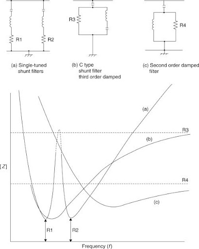
Harmonic filters are series or parallel resonant circuits designed to shunt or block harmonic currents. They reduce the harmonic currents flowing in the power system from the source and thereby reduce the harmonic voltage distortion in the system. Such devices are expensive and should only be used when other methods to limit harmonics have also been assessed. The application of filters in a given situation is not always straightforward. The filters themselves may interact with the system or with other filters to produce initially unsuspected resonances. Hence in all but the most simple cases harmonic studies should be used to assist with the determination of the type, distribution and rating of the filter group. Classical shunt filter circuits and their associated characteristics are shown in Fig. 24.5. Note that when the filter forms the capacitive section of an SVC, it is essential for it to be capacitive at fundamental frequency so it will produce the reactive power required.
Sign in to download full-size image
Figure 24.5
The selectivity or tuning response of the simple single resonant frequency filter circuit is defined by its Q or quality factor:
Q=ωLR
A high Q factor gives good selectivity (narrow frequency response) but the filter tuned circuit may be prone to drifting in its tuned frequency owing to changes in temperature or component ageing. Since slight changes in system frequency will cause detuning a less peaky filter response with a lower Q factor is more desirable to accommodate these changes. The tuned resonance frequency of a series LCR circuit is given by:
(24.10)
f=12π(1LC)
and the impedance at resonance is simply the residual reactor resistance, R. The detuning of filters for changes in harmonic frequency can be expressed as:
(24.11)
δ=ω−ωnωn=Δffn
If changes in capacitance and inductance, due to temperature change and ageing are included, the detuning factor becomes:
(24.12)
δ=Δffn+12(ΔLLn+ΔCCn)
Active filters may be employed to overcome such effects such that the filter is constantly kept in tune by automatically varying the reactor by means of a control system to keep the inductor and capacitor voltages equal.
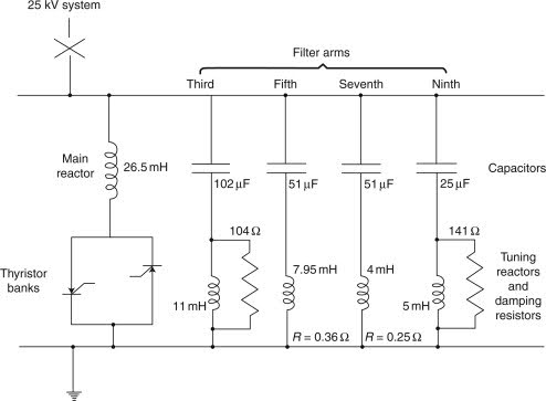
It is often the case that more than one harmonic is exceeding the harmonic limits set by the supply authority. Therefore more than one filter is necessary. However, as the number of shunt filters increases there is a tendency for these circuits to interact with the power system impedance to produce unwanted resonances involving other frequencies, if such harmonic frequencies exist on the system. A solution is to use a high pass shunt or C type filter arrangement, whereby all frequencies above a certain harmonic are shunted to ground. A typical filter group is shown in Fig. 24.6.
Sign in to download full-size image
Figure 24.6
The required optimum selectivity of the tuned filters depends upon the system impedance angle, Ø, at the point of filter connection and the detuning factor, δ. An approximation for a possible optimum Q value derived from a graphical construction by Arrillaga et al. [3, 4] is given by the expression:
(24.13)
Q=1+cosϕ2δsinϕ
Consider a converter connected to a 33 kV system with a 50 Hz+1% frequency supply where studies have shown that there is a need for fifth and seventh harmonic filters. Suppose also that these studies show the need for 2 MVAr of reactive compensation for the converter. This could be conveniently split into two 1 MVAr units to form the filters; the 1 MVAr capacitors being more than adequate for the filter duty. Assume that the temperature variation for the inductors and capacitors is 0.01% per degree Celsius and 0.04% per degree Celsius respectively with a possible ambient temperature variation of 20°C above normal. Then from Eq. (24.12):
δ=Δffn+12(ΔLLn+ΔCCn)=1100+12(0.0001×20+0.0004+20)=0.015
Now if the system impedance angle is 70 degrees, from Eq. (24.13):
Q=1+cos702(0.015sin70)=47.6
then for each capacitor
MVAr=V2XcandXc=106Ω2πfC(whereVisthelinevoltageinkV)C=MVAr2πfV2×106=106microfarads(µF)
Thus for the 5th harmonic:
C=1062πfV2=1062π250(33)2=0.584µFL=106(2πf)2C=0.694H
and hence
R=2π×250×0.69447.6=22.9Ω
and similarly for the 7th harmonic filter:
C=0.417µFL=0.496H
and
R=22.9Ω
The more complex calculations associated with parallel high pass and C type filters are given in the references at the end of this chapter.
Show more
Book
2012, Transmission and Distribution Electrical Engineering (Fourth Edition)
DrC.R. Bayliss CEng FIET, B.J. Hardy CEng FIET
Chapter
Pumping, Electrical Plant, Control and Instrumentation
19.25 Harmonic Filters
There are two types of harmonic filter:
Passive, where a series of inductors and capacitors try to filter the high frequency components, preventing them reaching the mains. This has the disadvantage that it is also affected by the external harmonics on the mains and can overheat. It is impossible to prevent the external harmonics from being absorbed by the filter and it is very hard to size such filters because the effect of the external harmonics cannot easily be identified and designed for.
Active, where a semiconductor based active front end (similar to a VSD active front end) detects and measures the harmonic frequencies generated by the drives and injects equal amounts of harmonic current in anti-phase to the generated harmonics. These cancel out resulting in an acceptable level of harmonics. One of the greatest benefits of these units is that they are controlled and current limited and will not exceed their thermal limits. This means that if the harmonics should increase the unit will not overheat, although it might not remove all of the primary harmonics. Since the unit is also microprocessor controlled, alarms can be automatically generated if this should occur. Some active units provide a broad adjustment over four or five harmonic frequencies whilst others allow individual frequencies to be targeted.
Book
2017, Twort’s Water Supply (Seventh Edition)
Malcolm J. Brandt BSc, FICE, FCIWEM, MIWater, … Don D. Ratnayaka BSc, DIC, MSc, FIChemE, FCIWEM
Chapter
Impact and management of power system harmonics
4.7.2 Harmonic filters
The purpose of harmonic filters is to either prevent the harmonic current from flowing through the network impedance, and as such reducing or eliminating the harmonic voltage or to eliminate the harmonic current entirely. Harmonic filtering is an option for both consumers and network operators. There are two filter technologies to be considered: passive filters and active filters.
In the case of passive filters, there are many designs in use (e.g. single tuned, double tuned, c-type). Regardless of the design, the theory behind passive filters is to provide a shunt circuit which presents as a low impedance to the harmonic orders which are to be filtered. In this case, the harmonic current will flow through this low impedance path instead of the higher network impedance path presented by the network resulting in lower voltage distortion. Passive harmonic filtering is achieved by designing a combination of capacitors and inductors that exhibit a series resonance (i.e. very low impedance) at the harmonic order which is to be filtered. In some cases it may also be possible to tune power factor correction capacitor banks to provide harmonic filtering. The process for this is similar to that used to detune the capacitor back as described in Section 4.4.1.4.
Active harmonic filters are power electronic devices which utilise switching components in order to generate waveforms which are completely out of phase for the harmonic order to be filtered. These out-of-phase waveforms will cancel the harmonic current thus eliminating the distortion. Active harmonic filters are more flexible than passive filters and also have the advantage of not altering the network impedance. However, they can be difficult to implement and are more expensive than passive filters.
Book
Sarath Perera, Sean Elphick
Chapter
Introduction to Power Quality
1.8.6 Harmonic Filters, APLCs, and UPQCs
One means of ensuring that harmonic currents of nonlinear components will not unduly interact with the remaining part of the power system is to place filters near or close to nonlinear loads. The main function of a filter is either to bypass harmonic currents, block them from entering the power system, or compensate them by locally supplying harmonic currents. Due to the lower impedance of the filter in comparison to the impedance of the system, harmonic currents will circulate between the load and the filter and do not affect the entire system; this is called series resonance. If other frequencies are to be controlled (e.g., that of arc furnaces), additional tuned filters are required.
Harmonic filters are broadly classified into passive, active, and hybrid structures. These filters can only compensate for harmonic currents and/or harmonic voltages at the installed bus and do not consider the power quality of other buses. New generations of active filters are active-power line conditioners that are capable of minimizing the power quality problems of the entire system.
Passive filters are made of passive components (inductance, capacitance, and resistance) tuned to the harmonic frequencies that are to be attenuated. The values of inductors and capacitors are selected to provide low impedance paths at the selected frequencies. Passive filters are generally designed to remove one or two harmonics (e.g., the 5th and 7th). They are relatively inexpensive compared with other means for eliminating harmonic distortion, but also suffer from some inherent limitations, including:
Interactions with the power system;
Forming parallel resonance circuits with system impedance (at fundamental and/or harmonic frequencies). This may result in a situation that is worse than the condition being corrected. It may also result in system or equipment failure;
Changing characteristics (e.g., their notch frequency) due to filter parameter variations;
Unsatisfactory performance under variations of nonlinear load parameters;
Compensating a limited number of harmonics;
Not considering the power quality of the entire system; and
Creating parallel resonance. This resonance frequency must not necessarily coincide with any significant system harmonic. Passive filters are commonly tuned slightly lower than the attenuated harmonic to provide a margin of safety in case there are some changes in system parameters (due to temperature variations and/or failures). For this reason filters are added to the system starting with the lowest undesired harmonic. For example, installing a seventh-harmonic filter usually requires that a fifth-harmonic filter also be installed.
Designing passive filters is a relatively simple but tedious matter. For the proper tuning of passive filters, the following steps should be followed:
Model the power system (including nonlinear loads) to indicate the location of harmonic sources and the orders of the injected harmonics. A harmonic power (load) flow algorithm (Chapter 7) should be used; however, for most applications with a single dominating harmonic source, a simplified equivalent model and hand calculations are adequate;
Place the hypothetical harmonic filter(s) in the model and reexamine the system. Filter(s) should be properly tuned to dominant harmonic frequencies; and
If unacceptable results (e.g., parallel resonance within system) are obtained, change filter location(s) and modify parameter values until results are satisfactory.
In addition to power quality improvement, harmonic filters can be configured to provide power factor correction. For such cases, the filter is designed to carry resonance harmonic currents, as well as fundamental current.
Active filters rely on active power conditioning to compensate for undesirable harmonic currents. They actually replace the portion of the sine wave that is missing in the nonlinear load current by detecting the distorted current and using power electronic switching devices to inject harmonic currents with complimentary magnitudes, frequencies, and phase shifts into the power system. Their main advantage over passive filters is their fine response to changing loads and harmonic variations. Active filters can be used in very difficult circumstances where passive filters cannot operate successfully because of parallel resonance within the system. They can also take care of more than one harmonic at a time and improve or mitigate other power quality problems such as flicker. They are particularly useful for large, distorting nonlinear loads fed from relatively weak points of the power system where the system impedance is relatively large. Active filters are relatively expensive and not feasible for small facilities.
Power quality improvement using filters, unified power quality conditioners (UPQCs), and optimal placement and sizing of shunt capacitors, are discussed in Chapters 9 and 10, respectively.
1.8.6.1 Application Example 1.7: Hand Calculation of Harmonics Produced by Twelve-Pulse Converters
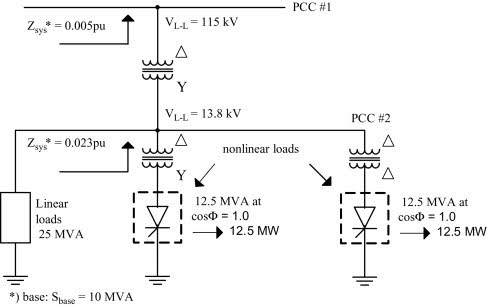
Figure E1.7.1 shows a large industrial plant such as an oil refinery or chemical plant [64] being serviced from a utility with transmission line-to-line voltage of 115 kV. The demand on the utility system is 50 MVA and 50% of its load is a twelve-pulse static power converter load.
Sign in to download full-size image
Figure E1.7.1
Table E1.7.1 lists the harmonic currents (Ih) given in pu of the fundamental current based on the commutating reactance Xch = 0.12 pu and the firing angle α = 30° of six-pulse and twelve-pulse converters. In an ideal twelve-pulse converter, the magnitude of some current harmonics (bold in Table E1.7.1) is zero. However, for actual twelve-pulse converters, the magnitudes of these harmonics are normally taken as 10% of the six-pulse values [64]. Assume RSCPCC#1=40 pu, and RSCPCC#2=8.7 pu.
Show more
Book
2015, Power Quality in Power Systems and Electrical Machines (Second Edition)
Mohammad A.S. Masoum, Ewald F. Fuchs
Chapter
Introduction to power quality
1.8.6 Harmonic filters, APLCs, and UPQCs
One means of ensuring that harmonic currents of nonlinear components will not unduly interact with the remaining part of the power system is to place filters near or close to nonlinear loads. The main function of a filter is either to bypass harmonic currents, block them from entering the power system, or compensate them by locally supplying harmonic currents. Due to the lower impedance of the filter in comparison to the impedance of the system, harmonic currents will circulate between the load and the filter and do not affect the entire system; this is called series resonance. If other frequencies are to be controlled (e.g., that of arc furnaces), additional tuned filters are required.
Harmonic filters are broadly classified into passive, active, and hybrid structures. These filters can only compensate for harmonic currents and/or harmonic voltages at the installed bus and do not consider the power quality of other buses. New generations of active filters are active-power line conditioners that are capable of minimizing the power quality problems of the entire system.
Passive filters are made of passive components (inductance, capacitance, and resistance) tuned to the harmonic frequencies that are to be attenuated. The values of inductors and capacitors are selected to provide low impedance paths at the selected frequencies. Passive filters are generally designed to remove one or two harmonics (e.g., the 5th and 7th). They are relatively inexpensive compared with other means for eliminating harmonic distortion, but also suffer from some inherent limitations, including:
Interactions with the power system.
Forming parallel resonance circuits with system impedance (at fundamental and/or harmonic frequencies). This may result in a situation that is worse than the condition being corrected. It may also result in system or equipment failure.
Changing characteristics (e.g., their notch frequency) due to filter parameter variations.
Unsatisfactory performance under variations of nonlinear load parameters.
Compensating a limited number of harmonics.
Not considering the power quality of the entire system.
Creating parallel resonance. This resonance frequency must not necessarily coincide with any significant system harmonic. Passive filters are commonly tuned slightly lower than the attenuated harmonic to provide a margin of safety in case there are some changes in system parameters (due to temperature variations and/or failures). For this reason filters are added to the system starting with the lowest undesired harmonic. For example, installing a seventh-harmonic filter usually requires that a fifth-harmonic filter also be installed.
Designing passive filters is a relatively simple but tedious matter. For the proper tuning of passive filters, the following steps should be followed:
Model the power system (including nonlinear loads) to indicate the location of harmonic sources and the orders of the injected harmonics. A harmonic power (load) flow algorithm (Chapter 8) should be used; however, for most applications with a single dominating harmonic source, a simplified equivalent model and hand calculations are adequate.
Place the hypothetical harmonic filter(s) in the model and reexamine the system. Filter(s) should be properly tuned to dominant harmonic frequencies.
If unacceptable results (e.g., parallel resonance within system) are obtained, change filter location(s) and modify parameter values until results are satisfactory.
In addition to power quality improvement, harmonic filters can be configured to provide power factor correction. For such cases, the filter is designed to carry resonance harmonic currents, as well as fundamental current.
Active filters rely on active power conditioning to compensate for undesirable harmonic currents. They actually replace the portion of the sine wave that is missing in the nonlinear load current by detecting the distorted current and using power electronic switching devices to inject harmonic currents with complimentary magnitudes, frequencies, and phase shifts into the power system. Their main advantage over passive filters is their fine response to changing loads and harmonic variations. Active filters can be used in very difficult circumstances where passive filters cannot operate successfully because of parallel resonance within the system. They can also take care of more than one harmonic at a time and improve or mitigate other power quality problems such as flicker. They are particularly useful for large, distorting nonlinear loads fed from relatively weak points of the power system where the system impedance is relatively large. Active filters are relatively expensive and not feasible for small facilities.
Power quality improvement using filters, unified power quality conditioners (UPQCs), and optimal placement and sizing of shunt capacitors, are discussed in Chapters 10 and 111011, respectively.
1.8.6.1 Application example 1.7: Hand calculation of harmonics produced by 12-pulse converters
Fig. E1.7.1 shows a large industrial plant such as an oil refinery or chemical plant [57] being serviced from a utility with transmission line-to-line voltage of 115 kV. The demand on the utility system is 50 MVA and 50% of its load is a 12-pulse static power converter load.
Table E1.7.1 lists the harmonic currents (Ih) given in pu of the fundamental current based on the commutating reactance Xch = 0.12 pu and the firing angle α = 30 degree of 6-pulse and 12-pulse converters. In an ideal 12-pulse converter, the magnitude of some current harmonics (bold in Table E1.7.1) is zero. However, for actual 12-pulse converters, the magnitudes of these harmonics are normally taken as 10% of the 6-pulse values [57]. Assume RSC | PCC # 1 = 40 pu, and RSC | PCC # 2 = 8.7 pu.
Solution to Application Example 1.7
Hand calculation of harmonics produced by 12-pulse converters
Calculating current harmonics at PCC #1:
Sph=V~I~3=50MVA3=16.67MVA
Vph=115kV3=66.4kV
Iph=SphVph=50MVA366.4kV=251A
IL = Iph = 251 A
At a short-circuit ratio of RSC=ISCIL=40 pu (at PCC #1)
The system’s impedance is Zsys (10 MVA base) = 0.5% = 0.005 pu,
ISCPCC # 1 = RSCIL = 40 ⋅ 251 A = 10040 A.
According to Table 1.7, for PCCs from 69 to 138 kV, the current harmonic limits should be divided by two. Therefore, for ISC/IL = (20–50):
Ihlimit=7.02=3.5%for5≤h<11;
Ihlimit=3.52≅1.8%for11≤h<17;
Ihlimit=2.52≅1.3%for17≤h<23.
The actually occurring harmonic currents are for Ispc = (251/2) A = 125.5 A for 12-pulse converter (SPC means static power converter):
I5actual=Ispc0.0192=125.50.0192=2.41A
I7actual=125.50.0132=1.65A
I11actual=9.16A
I13actual=7.15A
with IL = 251 A
I5actual%=I5actualIL100%.
I5actual%=0.96%I7actual%=0.66%]]allowed limitsare3.5%
I11actual%=3.65%I13actual%=2.85%]]allowed limitsare1.8%.
As can be seen, I11actual% and I13actual% are too large!
Calculating voltage harmonics at PCC #1:
Calculation of short-circuit (apparent) power SSC:
ISC = IL · RSC = 251(40) = 10,040 A
ISCIL=RSC
SSC=3⋅Vph⋅ISC=3115kV310.04kA=2000MVA
Checking:
SSC=MVASC=SbaseMVAZsystinperunitatbaseMVA=10MVA0.005pu=2000MVA.
Calculation of voltage harmonics (at PCC #1) for the current harmonics:
Vh=IhIbaseh⋅Zsyst⋅100%
Sbase = 10 MVA (all three phases)
Ibase=Sbase phaseVphase
Ibase=10MVA/3115kV/3=50.2A.
Harmonic (actually occurring) voltages:
V5=2.4150.250.005100%V5=0.120%V7=1.6550.270.005100%V7=0.115%V11=1.00%V13=0.93%]]allowed limit is1.5% for individual harmonic voltage (Table 1.8).
Also:
THDVlimit ≤ 2.5%
THDVactual=∑h=5,7,….HVh2Vphase100%=1.64%
Calculating current harmonics at PCC #2:
Sph=16.67MVA
Vph=13.8kV3=7.968kV
Iph=16.67MVA7.968kV=2092A
At a short-circuit ratio of RSC = ISCIL = 8.7 pu (at PCC #2)
The system’s impedance is Zsys10MVAbase=2.3%=0.023pu,
ISCPCC#2=RSC·IL=8.72092A=18.2kA.
Calculation of short-circuit current ISCphase:
Sphase=50MVA3=16.67MVA
Vphase=13.8kV3=7.97kV
Iphase=50MVA3⋅313.8kV=2.092kA
Iphase_converter=Iphase2=1.046kA
ISCphase = RSC ⋅ Iphase = 8.7(2.092) = 18.2 kA
RSC=ISCphaseIphase=18.22.092=8.7pu
Zsys = 2.3 % = 0.023 pu.
Actually occurring harmonic currents at PCC #2 for 12-pulse converter:
I5actual=10460.0192=20.08A
I7actual=10460.0132=13.81A
I11actual=10460.073=76.35A
I13actual=10460.057=59.62A
in percent
I5actual%=I5actualIphase100%
I5actual%=20.082092100%=0.96%
I7actual%=0.66%
I11actual%=3.65%I13actual%=2.85%]]above limitsseeanalysis forPCC#1.
Calculating voltage harmonics at PCC #2:
Vh=IhIbaseh⋅Zsyst⋅100%,
where
Ibase=10MVA/313.8kV/3=418.4A
V5=20.08418.450.023100%=0.552%V7=13.81418.450.023100%=0.531%below limit of3%
V11=4.61%V13=4.26%]]above limit of3%.
Note that on the 13.8 kV bus, the current and voltage distortions are greater than recommended by IEEE-519 (Table 1.8). A properly sized harmonic filter applied on the 13.8 kV bus would reduce the current distortion and the voltage distortion to within the harmonic current limits and the harmonic voltage limits on the 13.8 kV bus.
1.8.6.2 Application Example 1.8: Filter design to meet IEEE-519 requirements
Filter design for Application Example 1.7 will be performed to meet the IEEE-519 requirements. The circuit of Fig. E1.7.1 is now augmented with a passive filter, as shown in Fig. E1.8.1.
Solution to Application Example 1.8
Filter design to meet IEEE-519 requirements System analysis
At harmonic frequencies, the circuit of Fig. E1.8.1 can be approximated by the equivalent circuit shown in Fig. E1.8.2. This circuit should be analyzed at each frequency of interest by calculating series and parallel resonances.
For series resonance I~fh is large whereas for parallel resonance I~fh and I~sysh are large. The major impedance elements in the circuit respond differently as frequency changes. The impedance of the transmission line Zlineh is a complex relationship between the inductive and capacitive reactances. Using the fundamental frequency resistance R and inductance of the transmission line, however, gives acceptable results. For most industrial systems Zth and Zlineh can be approximated by the short-circuit impedance if low-frequency phenomena are considered.
The impedance vs frequency characteristic of a transformer
The impedance vs frequency characteristic of a transformer depends on its design, size, voltage, etc. Its load loss, I2R, will constitute 75%–85% of the total transformer loss and about 75% of this is not frequency dependent (skin effect). The remainder varies with the square of the frequency. The no-load loss (core loss) constitutes between 15% and 25% of the total loss and, depending on flux density, the loss varies as f3/2 to f3. From this, with the reactance increasing directly with frequency (inductance L is assumed to be constant), it can be seen that the harmonic (Xh/Rh) ratios will be less than the fundamental (h = 1) frequency (X1/R1) ratio, that is,
XhRh<X1R1.
If the fundamental frequency ratio (X1/R1) is used, there will be less damping of the high-frequency current than in actuality.
Adjacent capacitor banks
If there are large capacitor banks or filters connected to the utility system, it is necessary to consider their effect.
Converter as a harmonic generator
The converter is usually considered to be a generator of harmonic currents ih, and is considered to be a constant-current source. Thus Zconv is very large and can be ignored. If the converter is a constant-voltage source Zconv should be included.
Using Ohm’s and Kirchhoff’s laws (Fig. E1.8.2):
Zsysh=Zth+Zlineh
I~h=I~sysh+I~fh
I~fhZfh=I~syshZsysh,
or
I~fh=I~syshZsyshZfh
I~sysh=I~h−I~fh
I~sysh=I~h−I~syshZsyshZfh
or
I~sysh1+ZsyshZfh=I~h
I~syshZfh+ZsyshZfh=I~h
or
I~sysh=ZfhZfh+ZsyshI~h.
Correspondingly,
I~fh=ZsyshZfh+ZsyshI~h.
Define
ρsysh=ZfhZfh+Zsysh,
ρfh=ZsyshZfh+Zsysh.
Then
I~sysh=ρsyshI~h,
I~fh=ρfhI~h.
Because of
I~h=I~sysh+I~fh
ρsysh+ρfh=1.
Note that ρsysh and ρfh are complex quantities. It is desirable that ρsysh be small at the various occurring harmonics. Typical values for a series tuned filter are (at the tuned frequency hf1)
ρsysh=0.045∠–80.6°,for series tuned filters
ρfh=0.994∠+2.6°,for series tuned filters.
Parallel resonances occur between Zfh and Zsysh if ρsysh and ρfh are large at the tuned frequency (hf1). Typical values are
ρsysh=16.67∠–92.9°,
ρfh=16.75∠+83.6°.
The approximate 180 degree phase difference emphasizes why a parallel resonance cannot be tolerated at a frequency near a harmonic current generated by the converter: a current of the resonance frequency will excite the circuit and a 16.67 pu current will oscillate between the two energy storage units, the system impedance Zsysh and that of the filter capacitors Zfh.
A plot of ρsysh vs h is a useful display of filter performance. Frequently a plot of log(ρsysh) is more convenient. The harmonic voltage V~h is
V~h=ZsyshI~sysh=ZfhI~fh
V~h=ρsyshZfh+ZsyshI~fh
V~h=ρsyshZfh+ZsyshρfhI~h
V~h=ρsyshZfh+ZsyshZsyshZfh+ZsyshI~h
V~h=ρsysh⋅Zsysh⋅I~h,
or
V~h=ZfhZfh+ZsyshZfh+ZsyshZsyshZfh+ZsyshI~h
ZsyshZfh+Zsysh=ρfh
V~h=ρfh⋅ZfhI~h.
1.8.6.3 Application Example 1.9: Several users on a single distribution feeder
Fig. E1.9.1 shows a utility distribution feeder that has four users along a radial feeder [57]. Each user sees a different value of short-circuit impedance or system size. Note that
SSC=MVASC=10MVAZsyspuat10MVAbase.
There is one type of transformer (Δ – Y); therefore, only six-pulse static power converters are used.
Solution to Application Example 1.9
Several users on a single distribution feeder
Calculation of harmonic current for user #1 (case A, no filter):
SSC=350MVA
SSCphase=SSC3=116.67MVA
SSCphase=ISCphaseVphase
ISCphase=SSCphaseVphase=116.67MVA7.967kV=14.65kA
Sload=2.5MVA
Sloadphase=Sload3=0.833MVA
Iloadphase=SloadphaseVphase=0.833MVA7.967kV=104.7A.
For this user, there is a 25% static power converter (SPC) load:
IloadSPC=104.7A4=26.2A
RSC=ISCphaseIloadphase=14.65kA104.7A=140pu.
Therefore, harmonic currents for the six-pulse static power converter of user #1 are
I5A=26.20.192=5.03A→I5%=I5AIloadphase100%=5.03A104.7A100%=4.8%
I7A=26.20.132=3.46A→I7%=I7AIloadphase100%=3.46A104.7A100%=3.3%
I11[A] = 1.91 A → I11[%] = 1.82%
I13[A] = 1.49 A → I13[%] = 1.42 % .
Calculation of harmonic current for user #2 (case A, no filter):
SSC = 300 MVA
SSCphase=SSC3=100MVA
Vphase = 7.967 kV
ISCphase=SSCphaseVphase=100MVA7.967kV=12.56kA
Sload = 5 MVA
Sloadphase = 1.667 MVA
Iloadphase=SloadphaseVphase=209.5A
The 50% static power converter (SPC) load of this user yields:
IloadSPC = 104.73 A
RSC=ISCphaseIloadphase=12,560A209.5A=59.95pu
RSC ≈ 60 pu.
Therefore, harmonic currents for the six-pulse static power converter of user #2 are
I5A=104.730.192=20.11A→I5%=I5AIloadphase100%=20.11A209.5A100%=9.6%
I7A=104.730.132=13.82A→I7%=I7AIloadphase100%=13.82A209.5A100%=6.6%
I11[A] = 7.64 A → I11[%]= 3.65%
I13[A] = 5.96 A → I13[%] = 2.9 % .
Calculation of harmonic voltages Vh (case A, no filter):
The harmonic equivalent circuit of Fig. E1.9.1 in pu and ohms is shown in Fig. E1.9.2A and B, respectively. Using the harmonic equivalent circuits of Fig. E1.9.2:
Sbase=10MVA
Sbasephase=103MVA
Ibase=SbasephaseVphase=10MVA37.967kV=418.83A
Zbase=VphaseIbase=VbaseIbase
Note that Vbase = Vphase; therefore,
Zbase=7.9585kV418.83A=19Ω.
Voltage harmonics are computed using the total harmonic currents. For example, for the fifth harmonic:
I5#1=5.03AI5#2=20.11A]]I5#1+I5#2=25.13A.
The fifth voltage harmonic amplitudes for users 1 and 2 are:
V5PCCuser#1 = 4.18(5)(5.03) + 0.5428(5)(25.14) = 173.38 V
V5PCCuser#1=2.18%,
V5PCCuser#2 = 2.18(5)(20.11) + 0.5428(5)(25.14) = 287.46 V
V5PCCuser#2=3.61%.
The total fifth harmonic voltage is
V5PCCtot=0.5428525.14=68.26V
V5PCCtot=68.26V7.967kV100%=0.86%.
Show more
Book
Ewald F. Fuchs, Mohammad A.S. Masoum
Chapter
Utility Rate Structures and Grid Integration
4.7.2.2 Harmonic Filters
Power harmonic filters are mainly used to either block harmonic currents from flowing through electrical power distribution systems or locally isolate and cancel them (Fuchs and Masoum, 2008). Specifically, harmonic filters are designed to have low impedances to ensure that the harmonic currents are flowing between the loads and the filters, rather than reaching the power source and the other components of the electrical power generation and distribution systems. There are three main classifications of filters: (1) passive, (2) active, and (3) hybrid filters:
Passive filters are made up of reactive components like capacitors, inductors, and resistors. They are tuned to provide a low impedance path for specific currents with undesirable harmonic frequencies. Some potential issues can occur with passive systems if not properly selected resulting in resonance circuits parallel with power source leading to worse power quality conditions.
Active filters rely on active power conditioning electronic devices to compensate for unfavorable harmonic currents. Specifically, active filters correct for the distorted sinusoidal current waves to effectively eliminate harmonics. Active filters have the advantage to respond to dynamic changes in the electrical distribution systems (Fuchs and Masoum, 2008). Therefore, active filters can be considered for more complicated and critical systems because they have a better capability to act in response to drastic disturbances. They are, however, more expensive to install than passive filters.
Hybrid filters are combinations of active and passive filters. They are used in specific applications to take advantage of the benefits of both filters.
Book
2018, Optimal Design and Retrofit of Energy Efficient Buildings, Communities, and Urban Centers
Moncef Krarti
Chapter
Power Quality
40.3.3 Harmonic Filters
Harmonic filters come in many “shapes and sizes.” In general, harmonic filters are “shunt” filters because they are connected in parallel with the power system and provide low impedance paths to ground for currents at one or more harmonic frequencies. For power applications, shunt filters are almost always more economical than series filters (like those found in many communications applications) for the following reasons:
Series components must be rated for the full current, including the power frequency component. Such a requirement leads to larger component sizes and therefore costs.
Shunt filter components generally must be rated for only part of the system voltage (usually with respect to ground). Such requirements lead to smaller component sizes and therefore costs.
Shunt filters are designed (or can be purchased) in three basic categories as follows:
Single-tuned filters,
Multiple- (usually limited to double) tuned filters, and
Damped filters (of first-, second-, or third- order, or newer “c-type”).
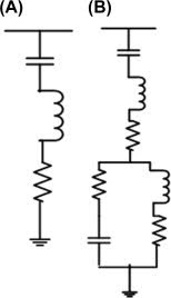
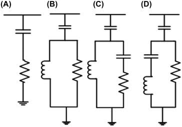
The single- and double-tuned filters are usually used to filter specific frequencies, while the damped filters are used to filter a wide range of frequencies. In applications involving small harmonic producing loads, it is often possible to use one single-tuned filter (usually tuned near the fifth harmonic) to eliminate problematic harmonic currents. In large applications, like those associated with arc furnaces, multiple tuned filters and a damped filter are often used. Equivalent circuits for single- and double-tuned filters are shown in Fig. 40.12. Equivalent circuits for first, second, third, and “c-type” damped filters are shown in Fig. 40.13.
Sign in to download full-size image
FIGURE 40.12
Sign in to download full-size image
FIGURE 40.13
A plot of the impedance as a function of frequency for a single-tuned filter is shown in Fig. 40.14. The filter is based on a 480 V, 300 kvar (three-phase) capacitor bank and is tuned to the 4.7th harmonic with a quality factor, Q, of 150. Note that the quality factor is a measure of the “sharpness” of the tuning and is defined as X/R where X is the inductive reactance for the filter inductor at the (undamped) resonant frequency; typically 50<Q<150 for tuned filters.
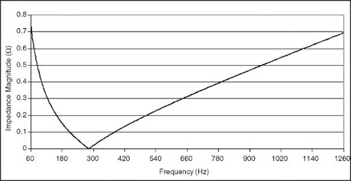
Sign in to download full-size image
FIGURE 40.14
A plot of impedance as a function of frequency for a second-order damped filter is shown in Fig. 40.15. This filter is based on a 480 V, 300 kvar capacitor bank and is tuned to the 12th harmonic. The quality factor is chosen to be 1.5. Note that the quality factor for damped filters is the inverse of the definition for tuned filters; Q=R/X where X is the inductive reactance at the (undamped) resonant frequency. Typically, 0.5<Q<1.5 for damped filters.
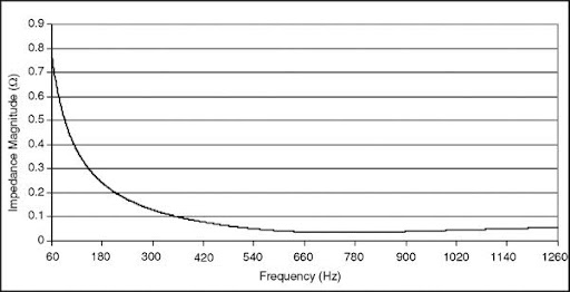
Sign in to download full-size image
FIGURE 40.15
In most cases, it is common to tune single-tuned filter banks to slightly below (typically around 5%) the frequency of the harmonic to be removed. The reasons for this practice are as follows:
For a low-resistance series resonance filter that is exactly tuned to a harmonic frequency, the filter bank will act as a sink to all harmonics (at the tuned frequency) in the power system, regardless of their source(s). This action can quickly overload the filter.
All electrical components have some non-zero temperature coefficient, and capacitors are the most temperature sensitive component in a tuned filter. Because most capacitors have a negative temperature coefficient (capacitance decreases and therefore tuned frequency increases with temperature), tuning slightly lower than the desired frequency is desirable.
Damped filters are typically used to control higher-order harmonics as a group. In general, damped filters are tuned in between the corresponding pairs of harmonics (11th and 13th, 17th and 19th, etc.) to provide the maximum harmonic reduction at those frequencies while continuing to serve as a (not quite as effective) filter bank for frequencies higher than the tuned frequency. Because damped filters have significantly higher resistance than single- or double-tuned filters, they are usually not used to filter harmonics near the power frequency so that filter losses can be maintained at low values.
Show more
Book
2011, Power Electronics Handbook (Third Edition)
- Mark Halpin, Angela Card
Chapter
Solar PV integration into bulk power systems
3.7 Harmonic filters
Solar PV inverters convert the DC power generated by the solar panels into grid-ready AC power. However, these inverters can inject harmonic distortion into the AC, which are undesired frequencies that may influence the performance of other connected devices and lead to issues with the electrical system. To ensure that solar PV systems adhere to electrical network guidelines and rules and regulations, harmonic filters are essential. Harmonic filters aid in minimizing the risk of harmonic problems that could arise from the operation of solar PV inverters, which can lead to harmonic challenges in many nations that have specific requirements for harmonic distortion levels in the electrical system [11]. Harmonic filters play an essential part in adhering to grid codes, which are necessary for avoiding penalties, fines, or disconnecting from the grid.
Harmonic filters are electrical devices designed to mitigate or eliminate harmonic distortion in power grids [12]. They frequently operate in parallel to the solar PV inverters and are tuned to specific harmonic frequencies to filter out unnecessary harmonics, allowing only the fundamental frequency (50–60 Hz) to pass through. Harmonic filters can be utilized in solar PV integration in many different kinds of techniques, including passive, active, and hybrid filters.
Passive filters: Passive harmonic filters reduce the frequency range of harmonics using passive elements like resistors, inductors, and capacitors. Although they are easy to install and affordable, they could not function as effectively under different load conditions.
Active filters: Active harmonic filters inject compensating currents into the system to neutralize harmonic currents generated by solar PV inverters, such as inverters. Compared to passive filters, they are more sophisticated, more expensive, and offer more flexibility and adaptability to varying grid conditions.
Hybrid filters: Hybrid filters offer a balanced approach between cost-effectiveness and efficiency through integrating passive and active filter technologies. Passive filters are often used to reduce lower-order harmonics and active filters to deal with higher-order harmonics.
Book
2024, Power Systems Operation with 100% Renewable Energy Sources
- Suresh, … Sharmeela Chenniappan
Chapter
High Voltage Direct Current Transmission
26.5.4 Harmonic Filters
HVDC current source LCCs generate voltage and current harmonics on both AC and DC sides of the link. Harmonic filters are therefore required to mitigate these effects to levels that meet network requirements. The filters are made up of capacitors and reactors with parallel resistances to provide relatively low Q tuned circuits. As previously stated they may also therefore provide a contribution to the reactive power requirements of current source HVDC schemes.
The lower order harmonics arising within current source converters may necessitate filter banks up to 20–30% of the converter ratings. The LCC HVDC also generates DC side harmonics, but whether DC filtering is essential will depend, in part, on whether the smoothing reactor, itself, provides sufficient DC harmonic attenuation. The large sizes of harmonic filters as well as reactive power supplies required for an HVDC LCC scheme can result in temporary over-voltages during converter blocking, fault clearing and other system disturbances as discussed in Section 26.9.
Low energy harmonics are less of a problem in VSCs and the harmonic filters are not required to provide any reactive power. The harmonic filters in these designs are primarily used to soften the voltage wave shape and hence reduce equipment stresses, EMI and minimize the effects of system resonances. Compared to the low order harmonic filters used in current source converter schemes the VSC filters are normally cheaper and more compact. Dedicated DC filters are usually installed if the DC cables are close to telecommunications lines where other mitigation methods are not feasible.
Book
2012, Transmission and Distribution Electrical Engineering (Fourth Edition)
DrC.R. Bayliss CEng FIET, B.J. Hardy CEng FIET
Chapter
Impact of power quality issues in residential systems
6.5.2 Harmonic filter
Commonly, shunt-type harmonic filters are used in PSs because they provide low impedance paths for currents to ground on one or more harmonic frequencies. Compared to series filters, shunt filters are preferable based on the economic aspects of PS applications.
A series filter that is connected in series requires high component sizes, which is costly. Series filter components are chosen based on their full current rating and power frequency.
A shunt filter that is connected in parallel requires small component sizes, which is economical. Shunt filter components are chosen based on system voltage.
Shunt filters are classified into three types:
Single-tuned filters
Multiple-tuned filters
Damped filters
Single- and double-tuned filters are commonly used to filter specific frequencies. Damped filters are mostly utilized to filter extensive frequency ranges. If residential applications contain small harmonic-generated loads, they are filtered by employing single-tuned filters to remove the problematic harmonic currents. For bulky applications, multituned and damped filters are mostly utilized. Fig. 6.11 shows single- and double-tuned filter circuit diagrams and Fig. 6.12 illustrates a damped filter-type circuit diagram.
Sign in to download full-size image
Figure 6.11
Sign in to download full-size image
Figure 6.12
The damped filter type is mostly used to control higher-order harmonics in the network. It contains higher resistance than single- and double-tuned filters, so this type of filter is not used to remove harmonics near a power frequency. Commonly, damped filters are used to reduce the 11th and 13th, 17th, 19th, etc. pairs of harmonics.
Show more
Book
2021, Power Quality in Modern Power Systems
- Senthil Kumar, … P. Pandiyan
Related terms:
- Energy Engineering
- Power Engineering
- Power Quality
- Wind Turbine
- Passive Filters
- Current Harmonic
- Harmonics
- Power Factor
- Reactive Power
- Total Harmonic Distortion
Recommended publications

Electric Power Systems Research
Journal

International Journal of Electrical Power & Energy Systems
Journal

Renewable and Sustainable Energy Reviews
Journal

Energy
Journal